
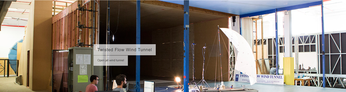
Twisted Flow Wind Tunnel
|
|
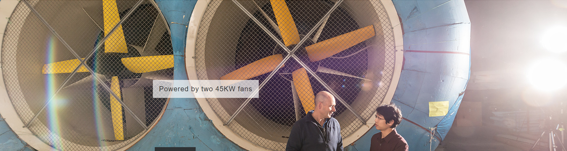
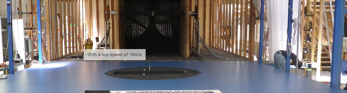
Twisted Flow Wind Tunnel Low speed testing High speed testing The wind tunnel is an open jet configuration. Wind is blown by two 3 m diameter fans through straightening screens down a 15 m long settling section. The air then passes through twisting vanes and into the working section. The model is connected, via supporting struts, to a force balance mounted below a turntable. The twisted structure of the wind required for testing sails is simulated using vanes which twist the horizontal wind direction. The twisting vanes comprise flexible sheets of material linked at their trailing edges by wires. These wires can be tensioned to twist the vanes by different amounts at each height. Digital outputs on the electric winches enable the settings to be calculated in advance and repeated accurately. The target atmospheric boundary layer can be simulated by adjusting the height of horizontal bars spanning the width of the settling chamber. This has the effect of slowing down the flow near "sea" level. Commercial testing for this tunnel is most commonly Sail Designers comparing the performance of different sails. However, because of the unique system which enables the walls of the tunnel to be adjusted, a wide range of other projects come to the TFWT for testing.
|
|